

We specialize in the R&D, design and manufacturing of hardware and software products for power safety, energy saving, power distribution and smart energy.
Categories
Popular Products
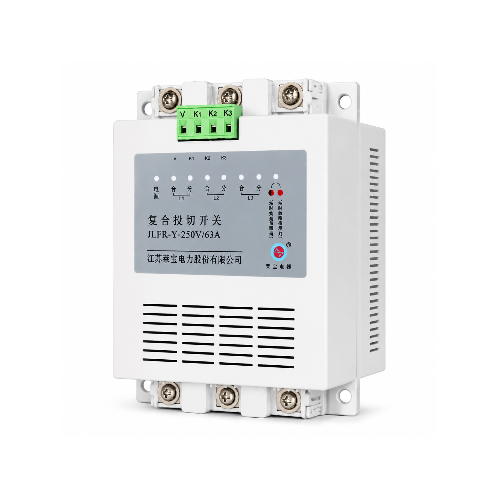
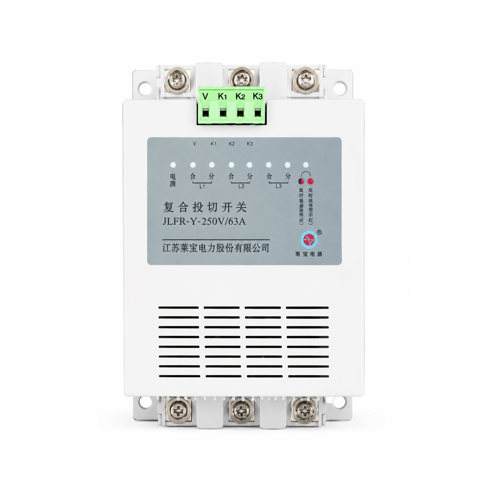
JLFK Series Hybrid Capacitor Switching Module
The JLFK series intelligent hybrid switching device is designed for switching power capacitors in low-voltage reactive power compensation systems operating at 50/60 Hz and rated voltages of 220 V or 380 V. Its operating principle involves connecting a thyristor in parallel with a magnetic latching relay;
Product Overview
The JLFK series intelligent hybrid switching device is designed for switching power capacitors in low-voltage reactive power compensation systems operating at 50/60 Hz and rated voltages of 220 V or 380 V. Its operating principle involves connecting a thyristor in parallel with a magnetic latching relay; this configuration combines the advantages of zero-crossing switching (via the thyristor) during the make-and-break moments with the zero-power-consumption characteristic of a mechanical contactor during steady-state operation. Key features include surge-free switching, silent and low-loss operation, and high stability and reliability.
Functional Features
① Zero-crossing switching: By connecting a thyristor switch in parallel with a high-current magnetic latching relay, the device achieves voltage zero-crossing turn-on and current zero-crossing turn-off. This ensures surge-free switching (limiting inrush current to within 1.5 times the rated current) during the make-and-break moments, while maintaining the zero-power-consumption benefit of a mechanical switch during steady-state operation.
② Utilizes microcontroller-based control for switching operations and intelligent monitoring of the operating status of thyristors, magnetic latching relays, input power, and loads, thereby providing comprehensive protection functions:
③ System voltage phase-loss protection: The switch refuses to close if the system power supply experiences a phase loss;
④ Power supply phase-loss protection: The switch refuses to close if the operating power supply experiences a phase loss;
⑤ Self-diagnostic protection: The system automatically monitors the operating status of thyristors and magnetic latching relays; if a fault is detected, the switch refuses to close or automatically disconnects;
⑥ Power outage protection: Automatically trips and disconnects in the event of a sudden power failure after engagement.
⑦ No harmonic injection: Conduction is initiated at the zero-crossing point via thyristors, followed by the engagement of magnetic latching relays after a brief delay; since the relays generate no harmonics during operation, harmonic injection is eliminated.
⑧ Low power consumption: The use of magnetic latching relays ensures that the control device consumes power only during the instant of switching, with zero consumption during steady-state operation. Furthermore, the low contact resistance of the magnetic latching relays prevents heat generation, eliminating the need for external heat sinks or fans and thereby reducing costs. This design completely prevents thyristor burnout and avoids interference with other electrical equipment operating nearby, truly achieving the goal of energy conservation and consumption reduction.
⑨ Photoelectric isolation between input signals and the composite switch ensures strong interference immunity and safe, reliable operation.
Technical Specifications
| Rated operating voltage | 380V, 220V AC ±20% |
| Voltage distortion rate | ≤5% |
| Operating power supply | 220V |
| Rated frequency | 50Hz ±5; |
| Service life | 100,000 operations |
| Maximum rated current | 100A |
| Control capacity | Three‑phase ≤40kvar (Delta connection); Single‑phase ≤15kvar (Y‑connection) |
| Contact voltage drop Circuit power consumption | ≤100mV ≤1.5VA |
| Response time | ≤1000ms |
| Contact withstand voltage | ≥1600V |
| Dimensions | 158mm × 102mm × 85mm; |
| Conduction impedance | ≤0.003Ω |
| Interval between switching operations Mounting cut‑out size | ≥1 second 77mm × 138mm |
| Interval between consecutive switch‑on operations | ≥60 seconds |
| Activation voltage | 8–18V DC; |
| Input resistance | ≥5.1kΩ |
| Insulation resistance | ≥10MΩ (under normal atmospheric conditions). |
Operating Conditions
① Altitude not exceeding 2,500 meters.
② Ambient air temperature: -25°C to +50°C.
③ Relative humidity: not exceeding 50% at 40°C; not exceeding 90% at 20°C.
④ The surrounding environment must be free from corrosive gases, conductive dust, and flammable or explosive media.
⑤ The installation site must be free from severe vibration.
⑥ Voltage distortion rate in the operating environment must not exceed 5%; otherwise, a series reactor is required.
More Products

Get a Free Quote
Feel free to contact us —
we strive to earn your trust.